
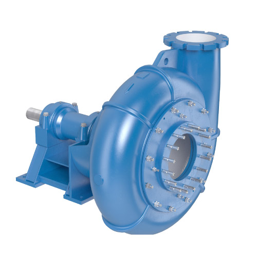
Type HCR
Qmax=1200m3/h – Hmax=36m
APPLICATION
HCR slurry pumps are used for pumping liquids containing substantial amounts of large particle sizes. Permissible pumped liquid density of 1700 kg/m3 is usual, but in individual cases, depending on the type of medium, pumping slurries of higher density at a limited speed is permitted. The maximum allowable size of particulate matter (passage size) reaches 180 mm.
HCR pumps are typically used in aggregate mining, in particular, working on suction dredgers used for mining of gravel located on the bottom of water reservoirs. They can also be used in other cases where the required pumping mixtures containing solids of significant size.
DESIGN
HCR pumps are single-stage horizontal rotary pumps of design adapted for pumping mixtures of liquids and solids of considerable size. The inlet connection port is at the pump axis and the discharge connection port in the basic version is directed vertically upwards laterally offset in relation to the axis of the pump. If needed by the requirements, it, a helical pump casing can be mounted in a different configuration in such a way that the discharge connection port is situated in every other position than vertical.
Taking into account the suction properties of the pump, HCR pump Pedestal is low, for the inlet port to be situated at the lowest position above the base. The hydraulic unit of HCR pumps consists of a helical casing and a front helical and rear plates, which are protected by protective walls. HCR pump impellers are closed and with low number (3-4) thickened vanes, which increases their lifetime and allows for the pumping larger size particles.
The parts that are in contact with the pumped medium (impeller, helical casing, and protective walls) are made from high chromium casts with high resistance to abrasion. Sealing joint slot between the front protective wall and the impeller is a radial slot, and its breadth due to wear can be adjusted without dismantling the pump by moving the entire rotating assembly together with the bearing casting from the pump pedestal by means of special adjustment screws. The expansion in the slot between the rear disc of the impeller and the impeller and the rear protection wall can be adjusted by moving the rear protective wall in relation to the casing by means adjustment screws.
In order to obtain a longer pump life, HCR pumps are designed for low speeds and are usually driven by a belt, although direct drive motor from low speed also is possible.
HCR pump bearings are designed to carry additional dynamic loads that may occur as a result of imbalance of rotating assembly as a result of its wear. The bearings are also envisaged to carry additional lateral loads that occur with the pulley drive. To this end rolling bearings lubricated with grease are used.
The shaft passage point through the casing is sealed by the cord packing with a water lock in order to prevent the penetration of water particles into the gland.
HCR pumps can be made in a vertical version.
MATERIALS OF CONSTRUCTION
Alloy steel cast is used for the flow elements. Cast iron is applied for bearing assembly. Alloy carbon steel cast and copper cast iron is used for the remaining castings.
|
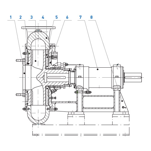
No. |
Part name |
| 1 | Suction flange |
| 2 | Front wear plate |
| 3 | Impeller |
| 4 | Casing |
| 5 | Rear wear plate |
| 6 | Stuffing box casing |
| 7 | Bearing assembly |
| 8 | Base |

|
Dimension [mm] |
Pump type |
|
|
HCR-250 |
HCR-300 |
|
| L | 1492 | 1502 |
| e | 210 | 246 |
| k | 485 | 475 |
| H | 1265 | 1480 |
| h | 450 | 450 |
| r | 640 | 725 |
| Ds | 300 | 350 |
| Dt | 250 | 300 |
|
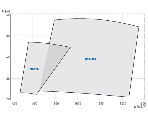
Pump type |
Capacity |
Head |
Rotation speed |
Shaft power |
Weight |
| HCR-250 | 800 | 42 | 700 | 142 | 2300 |
| HCR-300 | 1200 | 36 | 700 | 220 | 3100 |
The parameters are specified for clean water of density ρ=1000 kg/m3 and temperature T=15°C.