
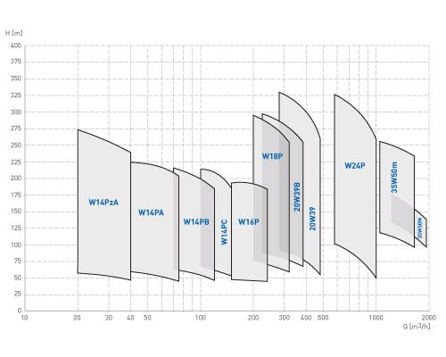
Type W
Qmax=1730m3/h – Hmax=150m
APPLICATION
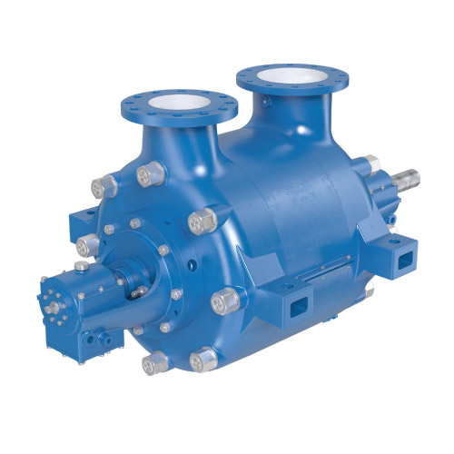
The W pumps are designed to handle hot, clean and industrial water, of temperature up to 150°C. They can be applied in water supply systems, industrial cooling systems, and for the ability to pump hot water, in district heating and power plants.
DESIGN
The W pumps are horizontal, stationary, multistage, ring-section pumps. The delivery flange is directed vertically upward and the suction flange is directed horizontally or vertically depending on the size of pump. Closed impellers and vane diffusers are applied. The axial thrust is absorber by a balance disk. The shaft seal can be sealed by a gland or mechanical seal.
MATERIALS OF CONSTRUCTION
The casings are made of cast iron. The impellers are made of cast steel or bronze.
Special material versions can be selected for handling non-typical fluids.
|
No. |
Part name |
No. |
Part name |
No. |
Part name |
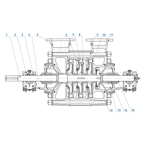
| 1 | Shaft | 6 | Stage casing | 11 | Discharge casing |
| 2 | Bearing housing cover | 7 | Impeller | 12 | Balance disk |
| 3 | Slide bearing | 8 | Diffuser | 13 | Stuffing box guard |
| 4 | Bearing casing | 9 | Tie bolt | 14 | Mechanical seal |
| 5 | Suction casing | 10 | Radial vane diffuser | 15 | Gland sleeve |
|
Pump |
Number |
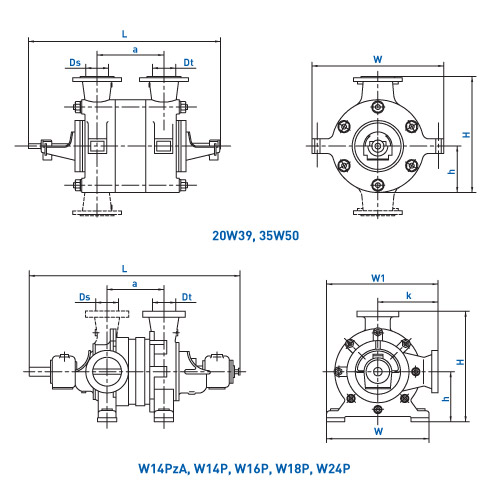
Dimensions [mm] |
||||||||
|
L |
a |
W1 |
W |
k |
H |
h |
Ds |
Dt |
||
| 20W39 | 2 | 1723 | 405 | – | 1050 | – | 930 | 380 | 250 | 200 |
| 3 | 1858 | 540 | ||||||||
| 4 | 1993 | 675 | ||||||||
| 5 | 2128 | 810 | ||||||||
| 6 | 2263 | 945 | ||||||||
| 35W50 | 2 | 2455 | 660 | – | 1600 | – | 1425 | 575 | 400 | 350 |
| 3 | 2690 | 895 | ||||||||
| W14PzA | 2 | 1340 | 250 | 695 | 650 | 370 | 650 | 280 | 125 | 100 |
| 3 | 1430 | 340 | ||||||||
| 4 | 1550 | 430 | ||||||||
| 5 | 1640 | 520 | ||||||||
| 6 | 1730 | 610 | ||||||||
| 7 | 1820 | 700 | ||||||||
| 8 | 1910 | 790 | ||||||||
| W14PA | 3 | 1477 | 370 | 695 | 650 | 370 | 650 | 280 | 150 | 125 |
| 4 | 1587 | 480 | ||||||||
| 5 | 1697 | 590 | ||||||||
| 6 | 1807 | 700 | ||||||||
| 7 | 1917 | 810 | ||||||||
| 8 | 2027 | 920 | ||||||||
| W14PB | 3 | 1477 | 370 | 695 | 650 | 370 | 650 | 280 | 150 | 125 |
| 4 | 1587 | 480 | ||||||||
| 5 | 1697 | 590 | ||||||||
| 6 | 1807 | 700 | ||||||||
| 7 | 1917 | 810 | ||||||||
| 8 | 2027 | 920 | ||||||||
| W14PC | 3 | 1477 | 370 | 695 | 650 | 370 | 650 | 280 | 150 | 125 |
| 4 | 1587 | 480 | ||||||||
| 5 | 1697 | 590 | ||||||||
| 6 | 1807 | 700 | ||||||||
| 7 | 1917 | 810 | ||||||||
| 8 | 2027 | 920 | ||||||||
| W16P | 2 | 1446 | 320 | 810 | 720 | 450 | 780 | 330 | 200 | 150 |
| 3 | 1576 | 450 | ||||||||
| 4 | 1706 | 580 | ||||||||
| 5 | 1836 | 710 | ||||||||
| 6 | 1966 | 840 | ||||||||
| W18P | 2 | 1710 | 375 | 885 | 810 | 480 | 845 | 365 | 250 | 200 |
| 3 | 1850 | 515 | ||||||||
| 4 | 1990 | 655 | ||||||||
| 5 | 2130 | 795 | ||||||||
| 6 | 2270 | 935 | ||||||||
| W24P | 2 | 2283 | 580 | 1275 | 1150 | 700 | 1240 | 540 | 350 | 300 |
| 3 | 2493 | 790 | ||||||||
| 4 | 2703 | 1000 | ||||||||
|
Pump |
Number |
Capacity |
Head |
Rotation Speed |
Shaft power |
Weight |
| w14PzA | 2 | 30 | 69 | 1500 | 18,5 | 483 |
| 3 | 104 | 30 | 545 | |||
| 4 | 128 | 30 | 607 | |||
| 5 | 160 | 37 | 670 | |||
| 6 | 192 | 45 | 732 | |||
| 7 | 224 | 45 | 794 | |||
| 8 | 256 | 55 | 856 | |||
| W14PA | 3 | 60 | 81 | 1500 | 30 | 630 |
| 4 | 108 | 37 | 735 | |||
| 5 | 135 | 45 | 840 | |||
| 6 | 162 | 55 | 945 | |||
| 7 | 189 | 75 | 1050 | |||
| 8 | 216 | 75 | 1155 | |||
| W14PB | 3 | 100 | 75 | 1500 | 30 | 630 |
| 4 | 100 | 45 | 735 | |||
| 5 | 125 | 55 | 840 | |||
| 6 | 150 | 75 | 945 | |||
| 7 | 175 | 75 | 1050 | |||
| 8 | 200 | 90 | 1155 | |||
| W14PC | 3 | 125 | 69 | 1500 | 45 | 630 |
| 4 | 104 | 55 | 735 | |||
| 5 | 130 | 75 | 840 | |||
| 6 | 156 | 90 | 945 | |||
| 7 | 161 | 110 | 1050 | |||
| 8 | 208 | 132 | 1155 | |||
| W16P | 2 | 200 | 64 | 1500 | 55 | 830 |
| 3 | 96 | 90 | 1000 | |||
| 4 | 128 | 132 | 1170 | |||
| 5 | 160 | 160 | 1340 | |||
| 6 | 192 | 200 | 1510 | |||
| W18P | 2 | 250 | 94 | 1500 | 110 | 1245 |
| 3 | 141 | 160 | 1475 | |||
| 4 | 188 | 200 | 1705 | |||
| 5 | 235 | 250 | 1940 | |||
| 6 | 282 | 315 | 2170 | |||
| 20W39B | 2 | 320 | 92 | 1500 | 132 | 1250 |
| 3 | 138 | 200 | 1410 | |||
| 4 | 184 | 250 | 1570 | |||
| 5 | 230 | 315 | 1730 | |||
| 6 | 276 | 355 | 1890 | |||
| 20W39 | 2 | 400 | 100 | 1500 | 160 | 1250 |
| 3 | 150 | 250 | 1410 | |||
| 4 | 200 | 315 | 1570 | |||
| 5 | 250 | 400 | 1730 | |||
| 6 | 300 | 500 | 1890 | |||
| W24P | 2 | 800 | 150 | 1500 | 400 | 3380 |
| 3 | 225 | 800 | 3610 | |||
| 4 | 300 | 1000 | 3850 | |||
| 35W50m | 2 | 1500 | 160 | 1500 | 900 | 4560 |
| 3 | 240 | 1250 | 5140 | |||
| 35W50M | 2 | 1730 | 150 | 1500 | 1000 | 4560 |
The parameters are specified for clean water of density ρ=1000 kg/m3 and temperature T=15°C.